5.1. Before Performing the Operational ChecksThere is a possibility that the image file written to the Flash memory in the factory default state is not the latest version. The latest image file can be downloaded from the Armadillo site. It is recommended to write the latest image file first. For details on rewriting the image file, see 8章Rewriting Image Files. The following explains about network configuration and applications that use the network. 5.2.1. Supported NetworksArmadillo-IoT can connect to multiple types of networks. The available network types and their corresponding network device names used in Linux is shown below. 表5.1 Networks and Network Devices | Network | Network Device | Notes |
|---|
| Wired LAN | eth0 | | | Wireless LAN | wlan0 | AEH-AR9462 | | 3G/LTE | ttyUSB2 | Quectel EC25 |
5.2.2. Network ConfigurationOn Armadillo-IoT Gateway G3, NetworkManager is used to configure network interfaces just like as with other standard Linux systems. By default NetworkManager automatically ups eth0 (Ethernet) and obtains network configuration with DHCP. NetworkManager manages all network settings as connections. Connections describe "How to connect to the network" and "How to create the network" and are saved in /etc/NetworkManager/system-connections/. Also, while it is possible to save multiple connections for each device, only one connection can be activated at one time. While NetworkManager also supports configuration using the traditional /etc/network/interfaces file, this document focuses on the use of nmcli. nmcli is a command line tool for operating NetworkManager. The format for nmcli is shown in 図5.1「nmcli Command Format」. From this, it can be seen that nmcli commands are entered with a format based on objects (OBJECT) and executing commands (COMMAND) on those objects. It's also possible to see that each object has help associated with it. See man nmcli for more information on each object. ![[注記]](images/note.png) | |
|---|
In addition to nmcli, the user-friendly nmtui is also installed on Armadillo-IoT, but it is not covered in this document. |
5.2.3. Basic Usage of nmcliThis section explains the basic usage of the nmcli. 5.2.3.1. List of ConnectionsTo check the list of registered connections, run the following command.[] NAME is also can be used as [ID]. 5.2.3.2. Enabling and Disabling ConnectionsTo enable a connection, run the following command. To disable a connection, run the following command. 5.2.3.3. Creating a ConnectionTo create a connection, run the following command. Enter the connection name (arbitary) for [ID], ethernet or wifi for [type], and interface name (device) for [interface name]. The specific connection creation method is explained in the chapter for each device. | |
|---|
A connection file is created with the name [ID] under /etc/NetworkManager/system-connections/. It is also possible to edit this with vi to modify the connection. |
5.2.3.4. Deleting a ConnectionTo delete a connection, run the following command. | |
|---|
The connection file under /etc/NetworkManager/system-connections/> is also deleted at the same time. |
5.2.3.5. Modifying a ConnectionThe following introduces specific ways to modify connections. ![[ティップ]](images/tip.png) | |
|---|
When wireless LAN or 3G/LTE configuration is edited with the nmcli connection modify command, the passphrase information is reset. When making the edits, please also set a passphrase at the same time. For details on how to set a passphrase for wireless LAN, see 「Wireless LAN」. For setting a passphrase for 3G/LTE, refer to 「Notes on Altering 3G/LTE Connection Settings」. |
![[警告]](images/warning.png) | |
|---|
Please consult a network administrator for help with network connections. |
An example of a DHCP configuration is shown in 図5.9「DHCP Configuration」. | |
|---|
As like with -ipv4.addresses, a set property can be deleted by adding '-' to the beginning of the property name. Conversely, a property can be added by specifying '+'. |
5.2.3.6. Applying Connection ModificationsWhen having modified a currently enabled connection, make sure to re-enable the connection. To check the device list (device name, type, status, valid connection), run the following command.[] 5.2.3.8. Connecting DevicesTo connect a device, run the following command. | |
|---|
To connect a device, a valid connection for the device is required. If the message "Error: neither a valid connection nor device given" is displayed, check if a valid connection exists by, for example, using the nmcli connection command. |
5.2.3.9. Disconnecting DevicesTo disconnect a device, run the following command. This section explains how to use wired LAN. 5.2.4.1. Creating a Wired LAN Interface (eth0) ConnectionTo create for a wired LAN interface connection, run the following command. 5.2.4.3. Confirming a Wired LAN ConnectionConfirm that normal communication is possible on the wired LAN. If the configuration has changed, be sure to re-enable the interface. Perform a PING with another network device on the same network. In the following example, it is assumed that the network device has an IP address of "192.0.2.20". | |
|---|
If any connections other than wired LAN are enabled, the wired LAN may not be used for network communication. In order to ensure that the wired LAN connection is used for the confirmation, disable the other connections in advance. |
This section explains how to use the wireless LAN module installed on Armadillo-IoT. As an example, connect to a WPA2-PSK(AES) access point. For details on how to connect to access points other than WPA2-PSK(AES), please refer to man nm-settings. In the explanation below, the ESSID of the access point is shown as [essid] and the passphrase as [passphrase]. 5.2.5.1. Connecting to a Wireless LAN Access PointTo connect to a wireless LAN access point, run the following command. | |
|---|
Depending on the access point being connected to, the following message may be displayed and you may not be able to connect to the access point. |
5.2.5.3. Confirming Wireless LAN ConnectionConfirm that it is possible to communicate properly over wireless LAN. Perform a PING with another network device on the same network. In the following example, it is assumed that the network device has an IP address of "192.0.2.20". | |
|---|
If any connections other than wireless LAN are enabled, the wireless LAN may not be used for network communication. In order to ensure that the wireless LAN connection is used for the confirmation, disable the other connections in advance. |
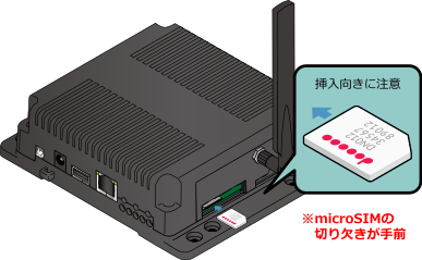
The following explains how to use the 3G/LTE module installed in Armadillo-IoT. 5.2.6.1. Before Configuring 3G/LTE Data CommunicationIn order to use 3G/LTE data communication a contract with a telecommunications carrier is needed. Prepare the MicroSIM (UIM card) and APN information provided by the carrier at the time of contract. | |
|---|
Make sure that the Armadillo-IoT is powered off before installing the MicroSIM (UIM card). |
| |
|---|
This product has a MicroSIM slot. Using a NanoSIM card with a SIM adapter or using a standard size SIM card cut to MicroSIM size may cause damaged to the MicroSIM slot. If this product is broken by using cards in this way it will not be covered by warranty even within the warranty period. |
Insert the microSIM (UIM card) with its notch facing the direction opposite to that of insertion and with the marked side facing up. The following information is necessary to configure the APN. 5.2.6.3. Establishing a 3G/LTE Data ConnectionTo establish a data connection without rebooting immediately after creating the 3G/LTE connection or changing its settings, execute the command shown in 図5.21「3G/LTE Data Connection」. 5.2.6.4. Confirming a 3G/LTE ConnectionConfirm that it is possible to communicate properly over 3G/LTE. Perform a PING with Atmark Techno's web server. If an internet connection is not available because of the use of a VPN connection and so on, please use a network device on the local network instead. | |
|---|
If any connections other than 3G/LTE are enabled, 3G may not be used for network communication. In order to ensure that the 3G connection is used for the confirmation, disable the other connections in advance. |
5.2.6.4.1. Ending a 3G/LTE Data ConnectionTerminate the 3G/LTE reconnection service before terminating the data communication with the nmcli command. If data communication is terminated without terminating the 3G/LTE reconnection service, the data connection will be restarted by that service. Stop the 3G/LTE reconnection service, and then end the data communication. 5.2.6.4.2. Restarting a 3G/LTE Data ConnectionStart the data communication. 5.2.6.4.3. Notes on Altering 3G/LTE Connection SettingsWhen wireless LAN or 3G/LTE configuration is edited with the nmcli connection modify command, the password information is reset. Execute the following command to set the password again each time. 5.2.6.5. 3G/LTE Reconnection ServiceThe 3G/LTE reconnection service periodically monitors the status of the 3G/LTE data connection and reconnects it when disconnection is detected. 5.2.6.5.1. Service SpecificationsWhen a MicroSIM is inserted and a valid NetworkManager 3G/LTE connection has been configured, it monitors the state of the connection once every 120 seconds. If the connection is disabled it is judged to be in a disconnected state and the connection is enabled. If the connection is enabled, a PING is executed to a specific destination. If the PING results in an error, it is judged to be in the disconnected state, and reconnection is performed by disabling and enabling the connection. If reconnection by disabling and enabling the connection fails more than once, it is judged that the 3G/LTE module is not operating normally and the power supply of the 3G/LTE module is cycled off and on on order to reconnect. 5.2.6.5.2. Factory SettingsIt is enabled in the default factory state, and the service starts automatically at system startup. The ping destination is "8.8.8.8" by default. Please change the configuration file (/etc/connection-recover/gsm-[wwan]_connection-recover.conf) appropriately for your environment. 5.2.6.5.3. Stop and StartTo stop the 3G/LTE reconnection service, run the following command. To start the 3G/LTE reconnection script, run the following command. ModemMamager and mmcli are explained here. Apart from NetworkManager which manages the network, ModemManager which manages the modem is installed on Armadillo-IoT. ModemManager operates mobile broadband devices (such as 3G/LTE modules) and manages their connection status. By using the mmcli command line tool of ModemManager, it is possible to acquire the 3G/LTE communication signal strength and SIM card information (telephone number, IMEI etc). Please refer to man mmcli for usage details of mmcli. 5.2.6.6.1. Obtaining a List of Recognized ModemsTo obtain a list of recognized modems, run the following command. 5.2.6.6.2. Obtaining Modem InformationTo obtain the status of the modem, run the following command. | |
|---|
In order to obtain modem information a MicroSIM must be inserted. Please make sure a MicroSIM is correctly inserted. |
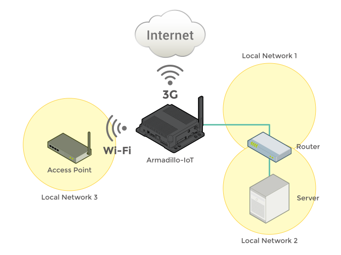
5.2.6.6.3. Obtaining MicroSIM InformationTo obtain MicroSIM information, run the following command. 5.2.6.6.4. Obtaining Communication Line InformationTo obtain communication line information, run the following command. 5.2.7. Configuration Example with NetworkManagerThe following introduces a configuration example with NetworkManager based on 図5.32「Network Structure Diagram」. 表5.5 Network Address Information | Node Name | Network Device | IP Address | Network Address |
|---|
| Armadillo | eth0 | 192.168.0.2 | 192.168.0.0/24 | | wlan0 | 172.16.xxx.xxx[] | 172.16.0.0/16[] | [wwan][] | xxx.xxx.xxx.xxx[] | xxx.xxx.xxx.xxx[] | | Router | eth0 | 192.168.0.1 | 192.168.0.0/24 | | eth1 | 192.168.10.1 | 192.168.10.0/24 | | Server | eth0 | 192.168.10.2 | 192.168.10.0/24 | | Access Point | eth0 | 172.16.0.1 | 172.16.0.0/16 |
5.2.7.1. Network Configuration ProcedureThe network setup procedure when configuring the network shown in 図5.32「Network Structure Diagram」 is as follows. Note that the created connection is saved in /etc/NetworkManager/system-connections/ and is activated even after restarting Armadillo. 手順5.1 Network Configuration Procedure Make sure that the state of eth0, [wwan] and wlan0 is disconnected. If any are in a state other than disconnected, change each to the disconnected state by following 表5.6「Making the Device State disconnected」. 表5.6 Making the Device State disconnected | Device State | Procedure |
|---|
| unmanaged | Check that the device settings are not included in /etc/network/interfaces. Remove them if they are. | | unavailable | Check that the LAN cable is not disconnected. Connect the cable if it is. | | connecting | A connection using the device is being enabled. Disable it by referring to 図5.4「Disabling a Connection」. | | connected | A connection using the device is enabled. Disable it by referring to 図5.4「Disabling a Connection」. |
Configure the wireless LAN (wlan0). Configure the wired LAN interface (eth0). Configure 3G/LTE Make sure that the state of eth0, [wwan], ppp0 and wlan0 is connected. Check the routing table.
A simple firewall is active on Armadillo. To display its configuration content execute the command shown in 図5.33「iptables」. 5.2.9. Network ApplicationsThe following explains about the network applications that can be used in the factory default image. | |
|---|
It is assumed that the network configuration of ATDE and Armadillo is the default state. If the network configuration has been modified please adjust for that as needed. |
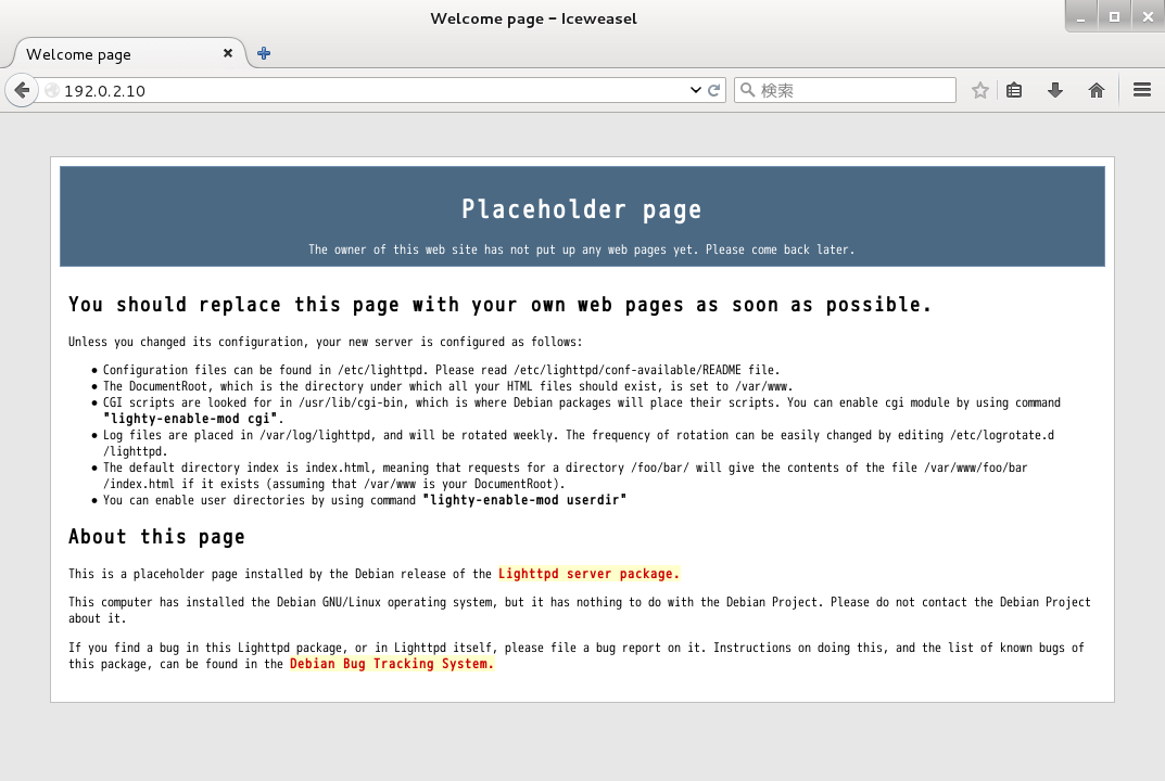
An HTTP server is active on Armadillo. When accessing the URL of Armadillo (http://[IP address of Armadillo]/) from a web browser on a PC such as ATDE, the top page (index.html) of lighttpd is displayed. The following devices are available for use as storage on Armadillo-IoT. 表5.7 Storage Devices | Device Type | Disk Device | First Partition | Interfaces |
|---|
| SD/SDHC/SDXC Cards | /dev/mmcblk*[] | /dev/mmcblk*p1 | SD Interface (CON4) | | USB Flash Memory | /dev/sd*[] | /dev/sd*1 | USB Host Interface (CON7) |
The following explains how to use storage by using an SDHC card as an example.SD/SDHC/SDXC cards are referred to as SD cards wherever the operations can be applied to any of them. | |
|---|
When using an SDXC/microSDXC card, it is necessary to format it in advance by referring to 「Changing and Formatting Storage Partitions」. This is because the Linux kernel cannot handle the exFAT file system. Normally, SDXC/microSDXC cards which have just been purchased are formatted with the exFAT file system. |
On Linux all accessible files and directories are brought together in one tree structure. Adding the file system of a storage device to this tree structure is called mounting. The mount command used to perform this mounting. The typical format of the mount command is as follows. The file system type is specified for fstype following the -t option[]. For the FAT32 file system use vfat[], and for the EXT4 file system use ext4. The device filename of the storage device is specified for device. For partition one of the SD card this will be /dev/mmcblk0p1 and for partition two it will be /dev/mmcblk0p2. The directory where the file system on the storage device is to be mounted is specified for dir. With the SDHC card inserted in the SD slot, execute the command shown in 図5.36「Mounting Storage」 to mount the SDHC card file system on the /mnt directory. Files in the SD card become visible under the /mnt directory. In order to safely remove storage it must be unmounted. The umount command is used to perform the unmounting. The directory where the device to unmount is mounted is specified as its option. 5.3.2. Changing and Formatting Storage PartitionsNormally, SDHC cards and USB memory just purchased have one partition and are formatted with the FAT32 file system. If you want to change the partition configuration, use the fdisk command. An example of using the fdisk command to divide the partition of an SD card configured with just that one partition into two partitions is shown in 図5.38「Altering Partitions with the fdisk Command」. After deleting the existing partition, two new primary partitions are created. 100Mbyte is allocated to the first partition and the remaining capacity to the second partition. The first partition becomes /dev/mmcblk0p1 and the second /dev/mmcblk0p2. For details on how to use the fdisk command, please refer to the man page etc. To format a storage device with the FAT32 file system, use the mkfs.vfat command. Likewise, for EXT3 use the mkfs.ext3 command and for EXT4 use the mkfs.ext 4 command. The command example for formatting partition one of the SD card with the EXT4 file system is shown below. As the Armadillo-IoT's LEDs are connected to GPIO they can be controlled in software. As the device driver is implemented as an LED class, the LEDs can be controlled with files under the LED class directory. The LED class directories and their corresponding LEDs are shown below. 表5.8 LEDs and LED Class Directories | LED Class Directory | Interfaces | Default Trigger |
|---|
| /sys/class/leds/led1/ | User LED1 | default-on | | /sys/class/leds/led2/ | User LED2 | default-on | | /sys/class/leds/led3/ | User LED3 | none | | /sys/class/leds/led4/ | User LED4 | none |
The locations of the user LEDs seen from the exterior of Armadillo-IoT are shown below. In the following explanation, the LED class directory representing an arbitrary LED is written as /sys/class/leds/[LED]. 5.4.1. Activating and Deactivating LEDsAn LED can be turned on and off by writing a value to the brightness file under the LED class directory. Valid values to write to brightness are between 0 and 255. Writing a value other than 0 to brightness turns the LED on. | |
|---|
Since the LEDs on Armadillo-IoT do not have brightness control functionality only two states, 0 (off) and 1-255 (on), can be specified. |
Writing 0 to brightness turns the LED off. The state of an LED can be obtained by reading brightness. A trigger to turn an LED on and off can be set by writing a value to the trigger file under the LED class directory. Valid values to write to the trigger file are shown below. 表5.9 trigger Types | Configuration | Description |
|---|
| none | No trigger is set. | | mmc0 | Act as the SD Interface (CON4) access lamp. | | mmc2 | Act as the eMMC access lamp. | | timer | Blink on and off at certain intervals. After setting this trigger, delay_on and delay_off files appear under the LED class directory which can be used to set the on and off times in millisecond increments. | | heartbeat | Blink on and off like a heart beat. | | default-on | Used mainly from the Linux kernel. The LED will turn on. |
When the following command is run, the LED will repeatedly turn on for two seconds and off for one second. The current trigger of the LED can be obtained by reading the trigger file. The value enclosed in [] is the current trigger. Armadillo-IoT uses the RTC functionality of the Board Management IC. To retain the time even if the power is turned off, an external battery (for example: CR1220) can be connected to the RTC backup interface (CON13). 5.5.1. Setting the Time on the RTCThere are two types of time on Linux: the system clock managed by the Linux kernel and the hardware clock managed by the RTC. In order to set the time in the RTC, first set the system clock. Following that, make the hardware clock match the system clock. The system clock is set using the date command. For the date command argument, specify the time to be set in the format [MMDDhhmmCCYY.ss]. The meaning of each field of the time format is as follows. 表5.10 Time Format Fields | Field | Meaning |
|---|
| MM | Months | | DD | Days (in month) | | hh | Hours | | mm | Minutes | | CC | First two digits of the year (optional) | | YY | Last two digits of the year (optional) | | ss | Seconds (optional) |
An example of setting it to 12:34:56 on June 2, 2015 is shown below. | |
|---|
If there is a time server on the network to which Armadillo-IoT is connected, the system clock can be set using the NTP (Network Time Protocol) client. The time zone can be changed with the timedatectl command. |
After setting the system clock, use the hwclock command to set the hardware clock. The device driver of the Armadillo-IoT user switches is implemented as an input device. Push and release events of the user switches can be obtained from the device file of the input device. The input device file of the user switches and the event code corresponding to each switch are shown below.
表5.11 Input Device Files and Event Codes | User Switches | Input Device File | Event Code |
|---|
| SW1 | /dev/input/event1 | 2 (KEY_1) | | SW2 | 3 (KEY_2) | | SW3 | 4 (KEY_3) |
| |
|---|
Input devices are indexed in the order in which they are detected. If an input device has been added by connecting a USB device etc., the index of the device file may be different. |
Here the evtest command is used to check the push and release events of the user switch. To stop evtest, enter Ctrl+c. The Armadillo-IoT temperature sensor uses the i.MX 7Dual's TEMPMON (Temperature Monitor). 5.7.1. Obtaining the TemperatureBy reading the value from the /sys/class/thermal/thermal_zone1/temp file, it is possible to obtain the measured temperature of the i.MX 7 Dual. Armadillo-IoT G3 can acquire the power supply voltage and the voltage of the external battery connected to the RTC backup interface (CON13) with the AD converter function of the BMIC (Board Management IC). 5.8.1. Obtaining the VoltageThe power supply voltage is divided and input to the AD converter. In order to acquire the power supply voltage, it is necessary to first acquire the input voltage to the AD converter. Since the voltage of the external battery is not divided, the input voltage of the AD converter will be the voltage of the external battery as-is. The AD converter is implemented as an IIO (Industrial I/O) device. The input voltage can be calculated from the file under /sys/bus/iio/devices/iio:device0/ directory. | |
|---|
The IIO device will be named iio:deviceN (N is a sequential number from '0') in the order in which the devices are detected. IIO devices can be identified from the IIO device name. The IIO device name of the BMIC's AD converter is "3-0012". |
The input voltage to the AD converter can be calculated from the AD conversion value and the minimum input voltage variation. The files under /sys/bus/iio/devices/iio:device0/ which are needed for calculating the input voltage are shown below. 表5.12 Files Needed for Calculating Input Voltage | File | Description |
|---|
| in_voltage0_raw | AD conversion value of single end input CH0 (power supply voltage) | | in_voltage1_raw | AD conversion value of single end input CH1 (external battery voltage) | | in_voltage_scale | Minimum input voltage variation of single end input |
As an example, the following describes how to obtain the power supply voltage. In example 図5.51「Obtaining the Input Voltage to the AD Converter」, you can see that the input voltage to the AD converter is about 1.261 V (1766 x 0.714111328 [mV]). The calculation formula for obtaining the power supply voltage from the input voltage to the AD converter is shown below. Taking 図5.51「Obtaining the Input Voltage to the AD Converter」 as an example, from the AD converter input voltage of 1.261V it can be determined that the power supply voltage is about 11.770V. | |
|---|
The power supply voltage can be displayed using the awk command as below. |
5.8.2. Monitoring Power Supply VoltageThe vintrigger command can be used to execute an arbitrary command when the power supply voltage reaches a specified voltage. | |
|---|
vintrigger cannot be run multiple times at once.
|
The vintrigger command help is as follows. The following shows an example of monitoring the power supply voltage at intervals of 30 seconds and turning on LED2 when the power supply voltage drops below 11000mV (11V). | |
|---|
The vintrigger command log is output to the /var/log/messages file. |
5.9. Armadillo-IoT RS232C Add-on Module RS00The Armadillo-IoT RS232C Add-on Module RS00 (hereafter referred to as the RS232C add-on module) has one RS232C level serial port. Since the device driver of the serial port of the RS232C add-on module is implemented as a TTY device, it can be controlled from the TTY device file. The add-on interface that connects the RS232C add-on module and the corresponding TTY device file is shown below. 表5.13 Add-on Interfaces and TTY Device Files | Add-on Interface | TTY Device File |
|---|
| CON1 | /dev/ttymxc0 | | CON2 | /dev/ttymxc1 |
| |
|---|
The RS232C Add-on Module is connected to CON1 in the development set's factory default state. |
| |
|---|
The add-on interface to which the RS232C add-on module is connected can be seen in the Linux kernel boot log. When connected to CON1, the output is as follows. |
5.10. Armadillo-IoT Isolated RS232C/422/485 Add-on Module RS01The Armadillo-IoT Isolated RS232C/422/485 Add-on Module RS01 (hereafter referred to as the isolated serial add-on module) has one electrically isolated RS232C/RS422/RS485 serial port on it. Since the device driver of the serial port of the isolated serial add-on module is implemented as a TTY device, it can be controlled from the TTY device file. The add-on interface that connects the isolated serial add-on module and the corresponding TTY device file is shown below. 表5.14 Add-on Interfaces and TTY Device Files | Add-on Interface | TTY Device File |
|---|
| CON1 | /dev/ttymxc0 | | CON2 | /dev/ttymxc1 |
| |
|---|
The add-on interface to which the isolated serial add-on module is connected can be seen in the Linux kernel boot log. When connected to CON1, the output is as follows. |
5.10.1. Changing RS422/RS485 Communication SettingsBefore turning on Armadillo-IoT, if the isolated serial add-on module SW1.1 is set to OFF, the RS485 configuration of the TTY device is automatically activated. | |
|---|
Do not change the setting of the insulated serial add-on module SW1.1 after turning on the Armadillo-IoT. Doing so may cause damage. |
RS485 settings that can be altered and the default values when automatically activated are shown in 表5.15「RS485 Setting and Default Values」. Flags shows the logical sum of each bit. 表5.15 RS485 Setting and Default Values | Configuration | Description | Default Value |
|---|
| flags | ENABLED (bit0) |
0: RS485 disabled
1: RS485 enabled
| 1 | | RTS_ON_SEND (bit1) |
0: RTS (Driver Enable) is low during data transmission
1: RTS (Driver Enable) is high during data transmission
| 1 | | RTS_AFTER_SEND (bit2) |
0: RTS (Driver Enable) is low outside of data transmission
1: RTS (Driver Enable) is high outside of data transmission
| 0 | | RX_DURING_TX (bit4) |
0: Half duplex
1: Full duplex
| 0 | | delay_rts_before_send | Delay time before transmission (ms) | 0 | | delay_rts_after_send | Delay time after transmission (ms) | 0 |
| |
|---|
Please do not change the default values of RTS_ON_SEND and RTS_AFTER_SEND of "flags". If changed, data transmission will no longer be possible. |
| |
|---|
It is not possible to use a TTY device with RS485 enabled as a console. |
The RS485 settings can be changed with an application program or Linux kernel startup options. For details on how to create an application program, refer to the document (Documentation/serial/serial-rs485.txt) included in the Linux kernel source code. For the Linux kernel startup options, RS485 is set with the following option specifiers. 表5.16 Setting RS485 from Linux kernel Boot Options | Option Specifier | Description |
|---|
| imx.rs485_uart1= |
Specify RS485 settings for UART1 (ttymxc0) connected to CON1.
| | imx.rs485_uart2= |
Specify RS485 settings for UART2 (ttymxc1) connected to CON2.
|
The format of the RS485 settings is as follows. As an example, to set the RS485 settings of the Isolated Serial Add-on Module connected to CON2 to full duplex communication, start up in Maintenance mode and run the following commands. 5.11. Armadillo-IoT Wi-SUN Add-on Module WS00The Armadillo-IoT Wi-SUN Add-on Module WS00 (hereafter referred to as Wi-SUN add-on module) is equipped with ROHM BP35A1. The Wi-SUN add-on module can be controlled from the TTY device file using ASCII commands. The add-on interface that connects the Wi-SUN add-on module and the corresponding TTY device file are shown below. 表5.17 Add-on Interfaces and TTY Device Files | Add-on Interface | TTY Device File |
|---|
| CON1 | /dev/ttymxc0 | | CON2 | /dev/ttymxc1 |
| |
|---|
The add-on interface to which the Wi-SUN add-on module is connected can be seen in the Linux kernel boot log. When connected to CON1, the output is as follows. |
5.11.1. Obtaining Configuration InformationAs an example of controlling the Wi-SUN add-on module, obtain the configuration information of BP35A1. The procedure for obtaining the configuration information of BP35A1 equipped on the Wi-SUN add-on module connected to the add-on interface (CON1) is shown below. 手順5.2 Obtaining Configuration Information Run the cu command and connect to /dev/ttymxc0. The baudrate is 115,200 bps. Running the SKINFO command results in the configuration information of BP35A1 being displayed. To quit cu, enter "~." (a tilde "~" followed by a dot ".").
For other ASCII commands and detailed information on BP35A1 please refer to ROHM documentation. 5.12. Armadillo-IoT Isolated RS485 Add-on Module RS02The Armadillo-IoT Isolated RS485 Add-on Module RS02 (hereafter referred to as the isolated RS485 add-on module) has one electrically isolated RS422/RS485 serial port on it. Since the device driver for the serial port of the isolated RS485 add-on module is implemented as a TTY device, it can be controlled from the TTY device file. The add-on interface that connects the isolated RS485 add-on module and the corresponding TTY device file are shown below. 表5.18 Add-on Interfaces and TTY Device Files | Add-on Interface | TTY Device File |
|---|
| CON1 | /dev/ttymxc0 | | CON2 | /dev/ttymxc1 |
| |
|---|
The add-on interface to which the isolated RS485 add-on module is connected can be seen in the Linux kernel boot log. When connected to CON1,the output is as follows. |
5.12.1. Changing RS422/RS485 Communication SettingsThe TTY device RS485 settings are applied automatically. RS485 settings that can be altered and the default values when automatically activated are shown in 表5.15「RS485 Setting and Default Values」. Flags shows the logical sum of each bit. 表5.19 RS485 Setting and Default Values | Configuration | Description | Default Value |
|---|
| flags | ENABLED (bit0) |
0: RS485 disabled
1: RS485 enabled
| 1 | | RTS_ON_SEND (bit1) |
0: RTS (Driver Enable) is low during data transmission
1: RTS (Driver Enable) is high during data transmission
| 1 | | RTS_AFTER_SEND (bit2) |
0: RTS (Driver Enable) is low outside of data transmission
1: RTS (Driver Enable) is high outside of data transmission
| 0 | | RX_DURING_TX (bit4) |
0: Half duplex
1: Full duplex
| 0 | | delay_rts_before_send | Delay time before transmission (ms) | 0 | | delay_rts_after_send | Delay time after transmission (ms) | 0 |
| |
|---|
Please do not change the default values of RTS_ON_SEND and RTS_AFTER_SEND of "flags". If changed, data transmission will no longer be possible. |
| |
|---|
It is not possible to use a TTY device with RS485 enabled as a console. |
The RS485 settings can be changed with an application program or Linux kernel startup options. For details on how to create an application program, refer to the document (Documentation/serial/serial-rs485.txt) included in the Linux kernel source code. For the Linux kernel startup options, RS485 is set with the following option specifiers. 表5.20 Setting RS485 from Linux kernel Boot Options | Option Specifier | Description |
|---|
| imx.rs485_uart1= |
Specify RS485 settings for UART1 (ttymxc0) connected to CON1.
| | imx.rs485_uart2= |
Specify RS485 settings for UART2 (ttymxc1) connected to CON2.
|
The format of the RS485 settings is as follows. As an example, to set the RS485 configuration of the isolated serial add-on module connected to CON2 to full duplex communication, start up in maintenance mode and execute the following command. 5.13. Armadillo-IoT Isolated Digital I/O / Analog Input Add-on Module DA00The Armadillo-IoT Isolated Digital I/O and Analog Input Add-on Module DA00 (hereafter referred to as the isolated I/O add-on module) consists of two electrically isolated digital input ports, two digital output ports and two 0 to 5V analog input ports. The digital I/O device driver for the isolated I/O add-on module is implemented as a GPIO device, and the analog input device driver is implemented as a IIO (Industrial I/O) device. 表5.21「Add-on Interfaces and GPIO Class Directories」 shows the add-on interface that connects the isolated IO add-on module and the corresponding GPIO class directory. The IIO device is iio:deviceN (N is a sequential number start from '0') in the order in which the devices are detected. 表5.21 Add-on Interfaces and GPIO Class Directories | Add-on Interface | Port | GPIO Class Directory |
|---|
| CON1 | Digital Output 1 | /sys/class/gpio/gpio89 | | Digital Output 2 | /sys/class/gpio/gpio90 | | Digital Input 1 | /sys/class/gpio/gpio141 | | Digital Input 2 | /sys/class/gpio/gpio140 | | CON2 | Digital Output 1 | /sys/class/gpio/gpio106 | | Digital Output 2 | /sys/class/gpio/gpio107 | | Digital Input 1 | /sys/class/gpio/gpio181 | | Digital Input 2 | /sys/class/gpio/gpio180 |
| |
|---|
The add-on interface to which the isolated I/O add-on module is connected can be seen in the Linux kernel boot log. When connected to CON2, the output is as follows. |
5.13.1. Setting the Digital Output StateThe output state can be set by writing a value to the value file under the GPIO class directory. "0" indicates open circuit, "1" indicates closed circuit. An example of setting the digital output of the isolated IO add-on module connected to the add-on interface (CON2) to open is shown below. 5.13.2. Getting the Digital Input StateThe input state can be obtained by reading the value from the value file under the GPIO class directory. "0" represents a connection to GND_ISO. "1" represents either open or the application of 3.15V or more. An example of obtaining the state of the digital input of the isolated IO add-on module connected to the add-on interface (CON2) is shown below. 5.13.3. Getting the Analogue Input VoltageThe input voltage can be calculated from the files under the /sys/bus/iio/devices/iio:device1/ directory. | |
|---|
The IIO devices are iio:deviceN (N is a sequential number from '0') in the order in which the devices are detected. IIO devices can be identified from the IIO device name. The IIO device name of the AD converter on the isolated IO add-on module is "mcp3202". |
The input voltage to the AD converter can be calculated from the AD conversion value and the minimum input voltage variation. The files under the /sys/bus/iio/devices/iio:device1/ directory required for calculating the input voltage are shown below. 表5.22 Files Needed for Calculating Input Voltage | File | Description |
|---|
| in_voltage0_raw | AD conversion value of single end input CH 0 | | in_voltage1_raw | AD conversion value of single end input CH 1 | | in_voltage_scale | Minimum input voltage variation of single end input | | in_voltage0-voltage1_raw | AD conversion value of the pseudo differential input | | in_voltage-voltage_scale | Minimum input voltage variation of pseudo differential input |
An example of calculating the input voltage to the single end input CH0 is shown below. In the 図5.58「Obtaining the Input Voltage to the AD Converter」 example, the input voltage to the single end input CH0 is 2.5 V (2048 x 1.220703125 [mV]). | |
|---|
The power supply voltage can be displayed using the awk command as below. |
| |
|