第3章 Before Turning on ArmadilloBefore using Armadillo, please prepare the following as required. - Work PC
A PC that runs either Linux or Windows which has a network interface and at least one USB port. Please refer to 「Setup of Environment for Development and Operational Checks」 and set up the development and operational check environment on the work PC. - Network Environment
Please connect the Armadillo and Work PC so that they can communicate via a network. - SD Card
Used when checking the operation of the SD slot. - USB Memory
Used when checking USB operation. - MicroSIM (UIM Card) and APN Information
These are used to confirm 3G/LTE operation. A contract with a telecommunications carrier is required. In order to check the operation of SMS, a MicroSIM (UIM card) with SMS function is required. - Software to Extract tar.xz Format Files
Used when creating the development and operational check environment. On Linux, tar[] can be used for the extraction. For Windows, 7-Zip and Lhaz etc can be used.
3.2. Setup of Environment for Development and Operational ChecksA VMware virtual machine data image is provided to allow easier software development and operational checks of Atmark Techno products. The VMware virtual machine data image is referred to as ATDE (Atmark Techno Development Environment). To start ATDEm, VMware virtualization software is used. The ATDE image data is compressed in the tar.xz format. Please extract it with the tools suitable for your environment. ![[ティップ]](images/tip.png) | |
|---|
In addition to VMware, Oracle VM VirtualBox is also a well know virtualization program. Oracle VM VirtualBox has the following features. It is possible to start ATDE with Oracle VM and use it as the software development environment, |
The Atmark Techno products supported differ depending on the ATDE version. The ATDE compatible with this product is ATDE7 v20180621 or later. ATDE7 is based on Debian GNU/Linux 9 (codename stretch) and the cross development tools necessary for software development and performing the operational checks of Armadillo-IoT Gateway are preinstalled. 3.2.1.1. Installing VMwareIn order to use ATDE, VMware must be installed on the work PC. Please refer to the VMware web page (http://www.vmware.com/) and install the VMware product that most suits the purpose of use. Also, as the image data of ATDE is compressed in the tar.xz format, please extract it with a tool suitable for your environment. ![[警告]](images/warning.png) | |
|---|
VMware offers a number of products, from free versions for non-commercial use to paid commercial use versions. Separate licenses and end-user license agreements (EULA) exist for each product, so please choose the most appropriate product after having fully checked these. |
| |
|---|
In order to avoid VMware and ATDE not working correctly, please check the following items from the VMware documentation. Hardware requirements of the host system Software requirements of the host system Processor requirements of the guest operating system
The documentation can be obtained from the VMware web site (http://www.vmware.com/). |
3.2.1.2. Obtaining the ATDE ArchiveThe ATDE archive can be obtained from the Armadillo site (http://armadillo.atmark-techno.com). | |
|---|
ATDE may not work properly depending on the operating environment of the work PC (hardware, VMware, ATDE supported architecture, etc). Please refer to the documentation for the VMware software you are using on the VMware web site (http://www.vmware.com/) and check the operating environment. |
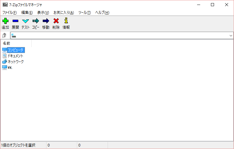
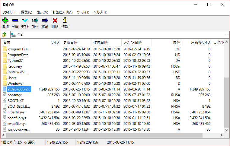
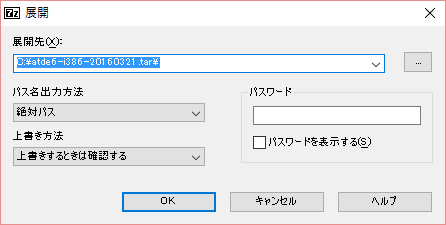
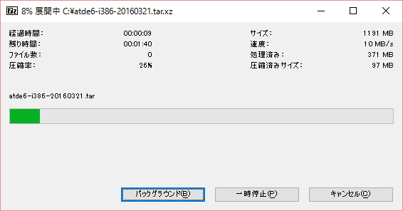
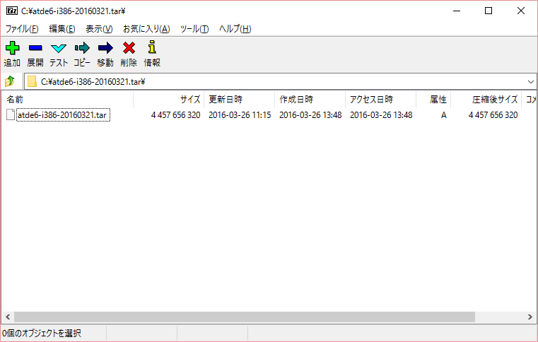
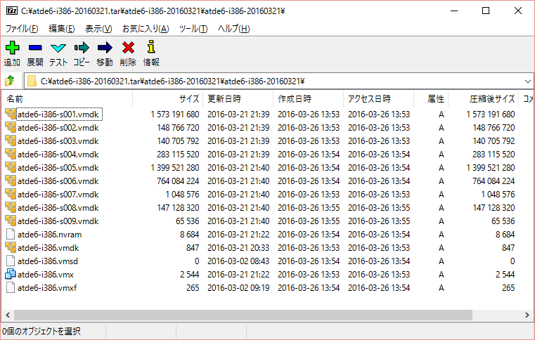
3.2.1.3. Extracting the ATDE ArchiveExtract the ATDE archive. The ATDE archive is a compressed file in the tar.xz format. The extraction method for Windows is shown in 手順3.1「Extracting the ATDE Archive on Windows」, and the method for Linux is shown in 手順3.2「Extracting the tar.xz Format File on Linux」. 手順3.1 Extracting the ATDE Archive on Windows Installing 7-Zip Install 7-Zip. 7-Zip can be obtained from the 7-Zip website (http://sevenzip.sourceforge.jp). Starting 7-Zip Start 7-Zip. Selecting the xz Compressed File Extract the xz compressed file into a file in the tar format. Select the tar.xz file and click "Extract". Specifying the xz Compressed File Extraction Destination Specify where to extract the file to and click "OK". Extracting the xz Compressed File The extraction begins. Selecting the tar Archive File Once the extraction of the xz compressed file has completed, a file in the tar format is created. Output the ATDE data image from the tar archive file with the same procedure as used for the tar archive file. Select the tar format file, click "Extract", specify the "Extracted location", and click "OK". Confirming Completion of the Extraction When extraction of the tar archive file is finished, the extraction of the ATDE archive is complete. The ATDE data image is output to the folder specified with "Extracted location".
手順3.2 Extracting the tar.xz Format File on Linux Extracting the tar.xz Compressed File Use the tar command with the Jxf options to extract the tar.xz compressed file. Confirming Completion of the Extraction When extraction of the tar archive file is finished, the extraction of the ATDE archive is complete. The ATDE data image is output to the atde-i386-[version] folder.
ATDE can be started by opening the virtual machine configuration (.vmx) file in the directory where you extracted the ATDE archive. Users which can be used to log on to ATDE are shown in 表3.1「Usernames and Passwords」[]. 表3.1 Usernames and Passwords | Username | Password | Permissions |
|---|
atmark | atmark | General user | root | root | Privileged user |
| |
|---|
ATDE can be used more effectively by increasing the memory size and number of processors assigned to it. For details on how to change the hardware settings of the virtual machine, refer to the documentation for the VMware software you are using on the VMware site (http://www.vmware.com/). |
3.2.2. Using Removable DevicesVMware supports the use of removable devices (such as USB devices and DVDs) with the guest operating system (ATDE). Depending on the device, these devices cannot be used simultaneously by the host operating system (the operating system running VMware) and the guest operating system. In order to use such a device in the guest operating system, it must be connected to the guest operating system. | |
|---|
For details on how to use removable devices, please refer to the documentation for the VMware software you are using on the VMware site (http://www.vmware.com/). |
In order to perform the operational checks of Armadillo-IoT, the devices shown in 表3.2「Removable Devices Used for Operational Checks」 must be connected to the guest operating system. 表3.2 Removable Devices Used for Operational Checks | Device | Device Name |
|---|
| USB serial converter | Future Devices FT232R USB UART | | Work PC physical serial port | Serial port |
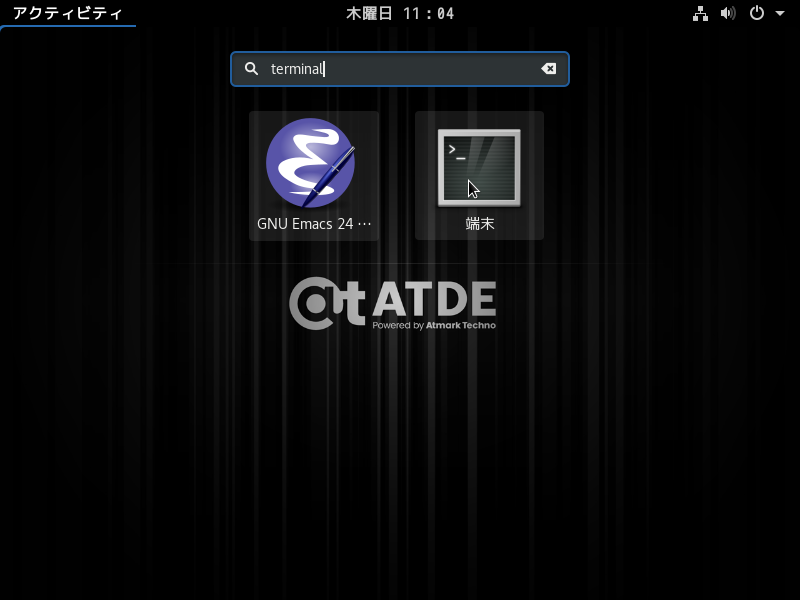
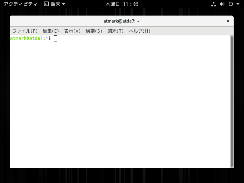
3.2.3. Starting the Command Line Terminal (GNOME Terminal)In ATDE, we start a command line terminal that provides a CUI (Character-based User Interface) environment. Various commands to be run on ATDE are input and executed with the command line terminal. While there are several types of command line terminals, here we start the GNOME terminal installed by default in the GNOME desktop environment. To start the GNOME terminal, please enter terminal from the activityin the upper left of the desktop like 図3.1「Starting the GNOME Terminal」 and select Terminal. A window opens as shown in 図3.2「GNOME Terminal Window」. 3.2.4. Using Serial Communication Software (minicom)Set the serial communication settings of the serial communication software (minicom) as shown in 表3.3「Serial Communication Configuration」. Also, please set the width of the terminal used to start minicom to 80 or more characters. The display may become disordered when entering commands if the width is less than 80 characters. 表3.3 Serial Communication Configuration | Item | Configuration |
|---|
| Baud rate | 115,200bps | | Data Length | 8-bit | | Stop Bit | 1-bit | | Parity | None | | Flow Control | None |
To start minicom configuration, please do as shown in 図3.3「Configuring minicom」. After configuration is completed, save it to the default setting (dfl) and exit. To start minicom, please do as shown in図3.4「Starting minicom」. ![[注記]](images/note.png) | |
|---|
Depending on the environment, the device file name may differ from that in the examples in this document and for example may be /dev/ttyS0 or /dev/ttyUSB1. |
To quit minicom, first enter Ctrl+a followed by the q key. After that, when the following is displayed, move the cursor to "Yes" and press Enter to quit minicom. | |
|---|
Enter Ctrl+a followed by the z key to display minicom's command help. |
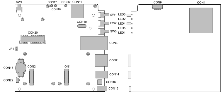
表3.4 Interfaces[] | Part Number | Interface Name | Form | Notes |
|---|
| CON1 | Add-on Interface 1 | Board-to-board connector 60 pin (0.5mm pitch) | Connection cycles: 40 times[] | | CON2 | Add-on Interface 2 | Board-to-board connector 60 pin (0.5mm pitch) | Connection cycles: 40 times[] | | CON4 | SD Interface | SD slot | | | CON6 | LAN Interface | RJ-45 Connector | | | CON7 | USB Host Interface | Type A connector | | | CON9 | Debug Serial Interface | Pin header 7 pin (1.25mm pitch) | Connection cycles: 40 times[] | | CON10 | WWAN Expansion Interface | Board-to-board connector 30 pin (0.5mm pitch) | Connection cycles: 50 times | | CON11 | MicroSIM Interface | MicroSIM Slot | | | CON13 | RTC Backup Interface 1 | Battery box | Compatible battery: CR1220 etc | | CON14 | Power Input Interface 1 | DC jack | Plug: Inner diameter 2.1mm, outer diameter 5.5mm | | CON15 | Power Input Interface 2 | Pin header 2 pin (2mm pitch) | | | CON16 | Power Output Interface | Pin header 2 pin (2mm pitch) | | | CON17 | 3G/LTE Antenna Interface1 | Small coaxial connector | Connection cycles: 30 times[] | | CON18 | 3G/LTE Antenna Interface2 | Small coaxial connector | Connection cycles: 30 times[] | | CON20 | WLAN Interface | PCI Express Mini Card connector | | | CON22 | RTC Backup Interface 2 | Pin header 2 pin (1.25mm pitch) | Connection cycles: 20 times[] | | JP1 | Boot Device Configuration Jumper | Pin header 2 pin (2.54mm pitch) | | | SW1 | User Switch 1 | Tact switch | | | SW2 | User Switch 2 | Tact switch | | | SW3 | User Switch 3 | Tact switch | | | SW4 | Reset Switch | Tact switch | | | LED1 | WWAN LED | LED (green, surface mounted) | | | LED2 | User LED2 | LED (green, surface mounted) | | | LED3 | User LED1 | LED (green, surface mounted) | | | LED4 | User LED3 | LED (green, surface mounted) | | | LED5 | User LED4 | LED (green, surface mounted) | |
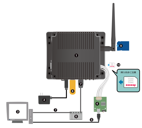
The following shows an example of connections between Armadillo-IoT Gateway and peripheral devices. | |
|---|
When using the AC adapter, connect the DC plug of the AC adapter to the Armadillo-IoT first and then plug the AC plug into the outlet.Wait at least 3 senconds after replugging power supply. |
| |
|---|
The microSIM interface not support hot swapping.Turning off the power when insert and remove the microSIM card. |
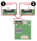
3.5. Slide Switch ConfigurationThe bootloader startup mode can be changed by operating the slide switch of the USB serial converter. The vi editor is a text editor that is installed by default on Armadillo. In this document the vi editor is used for editing the Armadillo's configuration files. Unlike the text editors such as gedit and emacs installed in ATDE, a major feature of the vi editor is that it has operating modes. It has a command mode and an input mode. All characters entered in command mode are treated as commands. In input mode, characters can be entered as text. Although the command examples shown in this chapter are written to be executed in ATDE, they can be executed on Armadillo in a similar way. To start vi, enter the following command. When the path of the filename is specified with file, the file will be edited (and the file will be created if file does not exist). vi starts in the command mode state. To enter characters, it is necessary to switch from command mode to input mode. To make this switch, enter the command shown in 表3.5「Commands to Enter Input Mode」. After entering input mode, characters are input as-is when their key is pressed. 表3.5 Commands to Enter Input Mode | Command | Operation |
|---|
| i | Start character input from the place where the cursor is located | | a | Start character input from after the cursor |
To return from the input mode to the command mode, press the ESC key. If you ever lose track of the current mode, just press the ESC key and return to the command mode once to avoid confusion. | Turning Off Japanese Conversion Functionality |
|---|
When entering a vi command please turn off the ATDE Japanese input system (Mozc). Turning the Japanese input system on and off can be done with half-width / full-width key. |
The starting position of character input when the "i" and "a" commands are entered is shown in 図3.10「Explanation of Commands for Switching to Input Mode」. | Delete Characters in vi |
|---|
Depending on the environment of the console, characters may not be deleted when using the BS (Backspace) key, with the "^ H" characters entered instead. In this case, delete characters using the command described in 「Deleting Characters」. |
The cursor can be moved with the arrow keys, but it is also possible to move the cursor by entering the commands shown in 表3.6「Commands to Move the Cursor」 in command mode. 表3.6 Commands to Move the Cursor | Command | Operation |
|---|
| h | Move one character to the left | | j | Move one character down | | k | Move one character up | | l | Move one character to the right |
3.6.5. Saving and QuittingThe commands for saving the file and quitting are shown in表3.8「Commands for Saving and Quitting」. 表3.8 Commands for Saving and Quitting | Command | Operation |
|---|
| :q! | Quit without saving changes | :w [file] | Save with the filename specified in file | | :wq | Save by overwriting the file and then quit |
Commands for saving and quitting start with ":" (colon). When entering the ":" key the cursor will move to the bottom of the screen and the entered command will be displayed. After entering the command, press Enter to execute the command. | |
|