第8章 Armadillo-440 LCD Expansion Board
The following provides details on the Armadillo-440 LCD Expansion Board hardware.
The Armadillo-440 LCD Expansion Board connects to the LCD interface on Armadillo-440 and includes a touch-screen LCD module, audio codec and real-time clock. The main specifications of the LCD Expansion Board and the LCD module itself are as follows.
表8.1 Armadillo-400 LCD Expansion Board Specifications
| LCD I/F |
General purpose LCD I/F connector x1
Data Image, Inc LCD (FG040360DSSWBG03) connector
Back-light LED driver
|
| Audio |
Wolfson codec (WM8978GEFL/V)
Stereo headphone output jack x1
Mono mic input jack x1
|
| Calendar Clock | Seiko Instruments RTC (S-35390A) with backup functionality |
| LED / Switch |
Tact Switch x 3
Power LED (green) x1
|
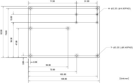
| Board Size | 106.0 × 82.0 mm (not including protrusions) |
| Power Supply Voltage |
Main power: DC3.3V
LCD back-light: DC2.8 - 5.5V
|
| Power Consumption | Approx. 0.8W (including LCD module) |
| Operating Temperature | -10 - 60℃ (with no condensation) |
表8.2 Compatible LCD Module Specifications
| Type | FG040360DSSWBG03 |
| Maker | Data Image, Inc |
| Type | TFT |
| Colors | 24bit |
| Screen Size | 4.3 inch |
| Backlight | LED (VL=15 - 18V, IL=40mA) |
| Touch Panel | 4-Wire Resistive |
| Dimensions | 105.5(W) x 67.2(H) x 4.2(D) mm |
| Active Area | 95.04(W) x 53.856(H) mm |
| Dot Pattern | 480 x (R, G, B) x 272 dots |
| Dot Pitch | 0.066(W) x 0.198(H) mm |
| Operating Temperature | -20 - 70℃ |
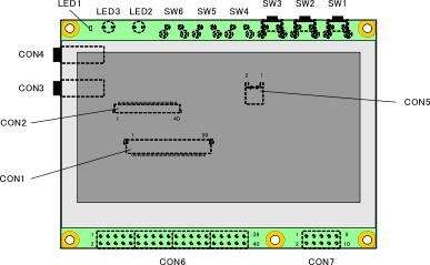
表8.3 LCD Expansion Board Interface Details
| Part Number | Interface | Shape | Notes |
|---|
| CON1 | Armadillo-440 Connection Interface | FFC Connector 50 pin (0.5mm pitch) | |
| CON2 | Data Image, Inc LCD Interface | FFC Connector 40 pin (0.5mm pitch) | |
| CON3 | Mono mic input jack | φ3.5mm mini jack | |
| CON4 | Stereo headphone output jack | φ3.5mm mini jack | |
| CON5 | Reserve terminal | 2 pin (2mm pitch) | Connector not mounted |
| CON6 | General Purpose LCD Interface[] | 40 pin (2.54mm pitch) | |
| CON7 | Reserve terminal | 10 pin (2.54mm pitch) | Connector not mounted |
| SW1, SW2, SW3 | User switch | Tact switch | |
| SW4, SW5, SW6 | Reserve switch | Tact switch | Switch not mounted |
| LED1 | Power LED (green) | Surface mounted LCD | |
| LED2, LED3 | Reserve LED | φ3mm LED | LED not mounted |
![[警告]](images/warning.png) | |
|---|
As CON1 and CON6 are connected to the same signal lines they cannot be used at the same time. Please disconnect the Data Image LCD from CON1 when connecting another LCD module to CON6. |
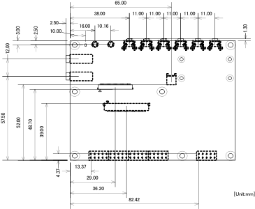
8.3. Board Outline Diagrams
8.4. About Defective LCD Pixels
Defective pixels occur at a certain rate due to the fundamental properties of LCD panels. The tolerance range of defective pixels in panels used on the Armadillo-440 LCD Expansion Board follow the standards set out below.
8.4.1. Pixel Defect Definitions
- Bright Dots
Pixels which appear brighter than surrounding pixels of the same color on an all-black screen display.
- Dark Dots
Pixels which appear darker than surrounding pixels of the same color on an all-white screen display.
- Continuous Dot Defects
Where multiple bright or dark dot defects occur continuously in one physical area. This applies to both bright-bright and dark-dark dot defects.
8.4.2. Examination Standard
表8.4 Defect Tolerance Range
| Defect | Tolerance Range |
|---|
| Bright Dot Defects | 4 |
| Dark Dot Defects | 5 |
| 2 Dot Continuous Defects | 2 groups (bright dots) 3 groups (dark dots) |
| 3 Or More Dot Continuous Defects | 0 (bright or dark dots) |
| Total Defects | 5 |