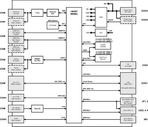
| Processor | Freescale i.MX257 (MCIMX257) |
| Processor Functions |
ARM926EJ-S Core
Instruction / Data Cache: 16KByte / 16KByte
Internal SRAM: 128KByte
Thumb code (16bit instruction set) support
|
| System Clock |
CPU Core Clock: 400MHz
BUS Clock: 133MHz
Oscillator Clock: 32.768kHz, 24MHz
|
| SDRAM |
LPDDR SDRAM: 64MByte (16bit width)
Micron MT46H64M16LFCK-6 IT
|
LPDDR SDRAM: 128MByte (16bit width)
Micron MT46H32M16LFBF-6 IT
|
| Flash Memory |
NOR Flash Memory: 16MByte (16bit width)
Numonyx PC28F128P30BF
Maximum Write Cycles: 100,000
|
NOR Flash Memory: 32MByte (16bit width)
Numonyx PC28F256P30BF
Maximum Write Cycles: 100,000
|
| Ethernet | 10BASE-T/100BASE-TX with AUTO-MDIX |
| Serial (UART) |
3 channels max[]
UART2:
RS232C level flow control pins (CTS, RTS, DTR, DSR, DCD, RI) Max baud rate: 230.4kbps
UART3[]/UART5[]:
|
4 channels max[]
UART2:
RS232C level flow control pins (CTS, RTS, DTR, DSR, DCD, RI) Max baud rate: 230.4kbps
UART3[]/UART4[]/UART5[]:
|
| USB |
2 channels (USB 2.0, Host)
USBOTG (USBPHY1):
USBHOST (USBPHY2):
|
| SD/MMC |
2 channels max[]
SDHC1: microSD slot
SDHC2[]: pin header
|
| LCD I/F |
|
Max resolution: SVGA (800x600), 18bpp
Connector Type: 50 pin FFC connector (0.5mm pitch)
|
| Touch Panel I/F |
| 4-Wire Resistive |
| Expansion I/F |
Audio I2S: 1 channel max[](AUD6[])
I2C: 1 channel max[](I2C2[])
SPI: 2 channels max[](CSPI1[], CSPI3[])
GPIO: 24bit max[]
|
Audio I2S: 2 channels max[](AUD5[], AUD6[])
I2C: 2 channels max[](I2C2[], I2C3[])
SPI: 2 channels max[](CSPI1[], CSPI3[])
Keypad Interface: 4 x 6 matrix (24 keys) max[][]
GPIO: 35bit max[]
|
| Switch | Tact Switch x1 |
| LED |
Red LED (φ3mm) x 1
Green LED (φ3mm) x 1
Yellow LED (surface mount) x 1
|
| Debug I/F | 8 pin (2.54mm pitch)[] |
| Board Size | 75.0 x 50.0mm (excluding protrusions) |
| Power Supply Voltage | DC3.1 - 5.25V[] |
| Power Consumption | 1.2W approx.[] |
1.2W approx. (Armadillo-440 only)[]
2.0W approx. (Armadillo-440 with LCD Expansion Board)[]
|
| Operating Temperature | -20 - 70℃ (with no condensation) |